5.运动控制基础课程
5.1 小车运动库文件分析
本节介绍了麦轮小车运动控制的编程实现,涵盖了电机初始化、速度控制以及转向、平移功能,用户可对相关的库文件进行了解。
5.1.1 程序运行效果
小车先直行,然后依次向左、向后、向右平移,再原地转、漂移后停止。
5.1.2 库函数简要分析
- 电机初始化函数Motor_Init()
该函数用来初始化电机引脚,通过在for循环来调用pinMode函数将电机I/O口工作模式设置为输出模式,并通过调用Velocity_Controller函数来设置小车为静止状态。
 /* 电机初始化函数 */
void Motor_Init(void){
  for(uint8_t i = 0; i < 4; i++){
 pinMode(motordirectionPin[i], OUTPUT);
  }
  Velocity_Controller( 0, 0, 0, 0);
}- 电机设置函数Motors_Set()
该函数根据传入参数的值来调整小车各个轮子的转速以及方向。在for循环中,首先根据解算后的结果对小车的转向进行调整,其次通过map函数将解算数值从0~100映射到10~255的范围,最后通过digitalWrite和analogWrite函数设置电机转向和转速。
/**
 * @brief PWM与轮子转向设置函数
 * @param Motor_x作为PWM与电机转向的控制数值。根据麦克纳姆轮的运动学分析求得。
 * @retval None
 */
void Motors_Set(int8_t Motor_0, int8_t Motor_1, int8_t Motor_2, int8_t Motor_3) {
  int8_t pwm_set[4];
  int8_t motors[4] = { Motor_0, Motor_1, Motor_2, Motor_3};
  bool direction[4] = { 1, 0, 0, 1};///< 前进 左1 右0
  for(uint8_t i; i < 4; ++i) {
 if(motors[i] < 0) direction[i] = !direction[i];
 else direction[i] = direction[i];

 if(motors[i] == 0) pwm_set[i] = 0;
 else pwm_set[i] = map(abs(motors[i]), 0, 100, pwm_min, 255);

 digitalWrite(motordirectionPin[i], direction[i]);
 analogWrite(motorpwmPin[i], pwm_set[i]);
  }
}- 电机速度控制函数Velocity_Controller()
这个函数,包含四个参数:方向、速度、自转速度和是否开启漂移。函数内部计算每个电机的速度并调用 Motors_Set 函数来设置电机的PWM值和方向。函数中使用了三角函数来计算基于方向的电机速度。此外,还考虑了自转速度和漂移功能的影响。
void Velocity_Controller(uint16_t angle, uint8_t velocity,int8_t rot,bool drift) {
  int8_t velocity_0, velocity_1, velocity_2, velocity_3;
  float speed = 1;
  angle += 90;
  float rad = angle * PI / 180;
  if (rot == 0) speed = 1;///< 速度因子
  else speed = 0.5;
  velocity /= sqrt(2);
  if (drift) {
 velocity_0 = (velocity * sin(rad) - velocity * cos(rad)) * speed;
 velocity_1 = (velocity * sin(rad) + velocity * cos(rad)) * speed;
 velocity_2 = (velocity * sin(rad) - velocity * cos(rad)) * speed - rot * speed * 2;
 velocity_3 = (velocity * sin(rad) + velocity * cos(rad)) * speed + rot * speed * 2;
  } else {
 velocity_0 = (velocity * sin(rad) - velocity * cos(rad)) * speed + rot * speed;
 velocity_1 = (velocity * sin(rad) + velocity * cos(rad)) * speed - rot * speed;
 velocity_2 = (velocity * sin(rad) - velocity * cos(rad)) * speed - rot * speed;
 velocity_3 = (velocity * sin(rad) + velocity * cos(rad)) * speed + rot * speed;
  }
  Motors_Set(velocity_0, velocity_1, velocity_2, velocity_3);
}
5.2 小车前进和转向
本节通过控制M1~M4四个电机的转动方向来控制小车前进和左右转动。
5.2.1 运动原理
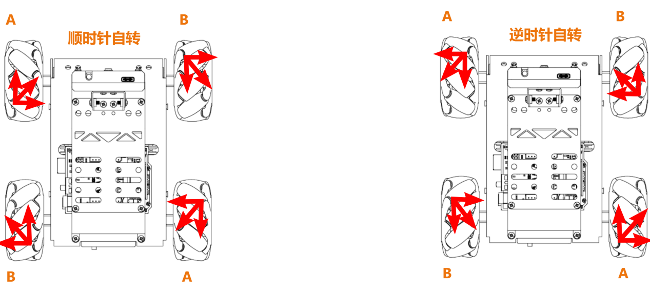
根据麦克纳姆轮的特性,小车前进时,四个轮子都必须正转;当小车左边的轮子反转,右边的轮子正转时,小车会原地逆时针旋转;当小车左边的轮子正转,右边的轮子反转时,小车会原地顺时针旋转。如以下受力分析图:
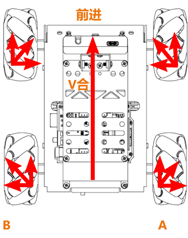
根据物理运动学知识可知,大小相等,方向相反的力可以互相抵消,假设A轮和B轮正转的速度一样快,那么A轮分解出向右的力和B轮分解出向左的力刚好互相抵消,合力方向向前,根据牛顿第二运动定律(F=ma)可知,加速度方向向前,则最终合速度“V合”方向也向前,其他方向的速度解析也是以同样的思路来推导。
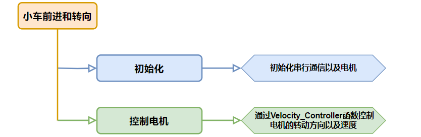
5.2.2 实现流程
5.2.3 程序下载
NOTE
下载程序前需先将蓝牙模块取下,否则会因串口冲突导致程序下载失败。
- 在本文档同路径"02 程序文件/小车前进和转向程序"下找到“forward_and_back/forward_and_back.ino”程序文件。

将Arduino通过UNO数据线(Type-B)连接至电脑。
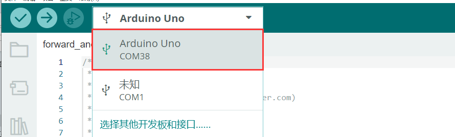
点击“选择开发板”选项,软件会自动检测当前Arduino的串口,点击进行连接。
- 点击
 ,将程序下载至Arduino中,等待下载完成即可。


5.2.4 实现效果
程序下载完成后,将小车开机,小车将前进1S->左转1S->右转1S。
5.2.5 程序分析
- 定义引脚及创建对象
- 定义
motorpwmPin数组,存储4个电机的PWM控制引脚号;定义motordirectionPin数组,用于存储4个电机的方向控制引脚号。
#include <Arduino.h>

const static uint8_t pwm_min = 50;
const static uint8_t motorpwmPin[4] = { 10, 9, 6, 11};///< 控制轮子速度引脚
const static uint8_t motordirectionPin[4] = { 12, 8, 7, 13}; ///< 控制轮子方向引脚- 声明了三个函数原型,
Motor_Init电机初始化、Velocity_Controller速度控制、Motors_Set设置电机速度。
void Motor_Init(void);
void Velocity_Controller(uint16_t angle, uint8_t velocity,int8_t rot,bool drift);
void Motors_Set(int8_t Motor_0, int8_t Motor_1, int8_t Motor_2, int8_t Motor_3);- setup()初始化及运动控制
- 初始化串行通信,设置串行通信读取数据超时时间为500ms;调用
Motor_Int()函数初始化电机。
void setup() {
  Serial.begin(9600);
  // 设置串行端口读取数据的超时时间
  Serial.setTimeout(500);
Motor_Init(); ///< 电机初始化- 调用
Velocity_Controller函数,设置电机以直行模式运行,速度为100,然后等待1秒。
  Velocity_Controller(0,100,0,0);   ///< 直行
delay(1000);- 调用
Velocity_Controller函数,设置电机以原地左转模式运行,旋转速度为100,然后等待1秒。
  Velocity_Controller(0, 0,100,0);  ///< 原地左转
delay(1000);- 调用
Velocity_Controller函数,设置电机以原地右转模式运行,旋转速度为-100,然后等待1秒。
  Velocity_Controller(0, 0,-100,0); ///< 原地右转
delay(1000);- 调用
Velocity_Controller函数,设置电机静止。
  Velocity_Controller(0,0,0,0);     ///< 静止
}- Motor_Init()电机初始化函数
初始化了电机的方向引脚为输出模式,调用Velocity_Controller函数,设置电机静止。
void Motor_Init(void){
  for(uint8_t i = 0; i < 4; i++){
    pinMode(motordirectionPin[i], OUTPUT);
  }
  Velocity_Controller( 0, 0, 0, 0);
}- Velocity_Controller()速度控制函数
- 初始化4个电机的速度值为整形,设置速度因子为1,将angle设为90°用于修正机器人方向,接着将angle从度转换为弧度。
void Velocity_Controller(uint16_t angle, uint8_t velocity,int8_t rot,bool drift) {
  int8_t velocity_0, velocity_1, velocity_2, velocity_3;
  float speed = 1;
  angle += 90;
float rad = angle * PI / 180;- 判断rot是否为0,若为0,则设置speed为1,否则设置speed为0.5。
  if (rot == 0) speed = 1;///< 速度因子
else speed = 0.5;- 减小速度值。
velocity /= sqrt(2);- 根据drift的值计算4个电机的速度。
  if (drift) {
    velocity_0 = (velocity * sin(rad) - velocity * cos(rad)) * speed;
    velocity_1 = (velocity * sin(rad) + velocity * cos(rad)) * speed;
    velocity_2 = (velocity * sin(rad) - velocity * cos(rad)) * speed - rot * speed * 2;
    velocity_3 = (velocity * sin(rad) + velocity * cos(rad)) * speed + rot * speed * 2;
  } else {
    velocity_0 = (velocity * sin(rad) - velocity * cos(rad)) * speed + rot * speed;
    velocity_1 = (velocity * sin(rad) + velocity * cos(rad)) * speed - rot * speed;
    velocity_2 = (velocity * sin(rad) - velocity * cos(rad)) * speed - rot * speed;
    velocity_3 = (velocity * sin(rad) + velocity * cos(rad)) * speed + rot * speed;
}- 使用计算得到的4个电机的速度值设置电机。
  Motors_Set(velocity_0, velocity_1, velocity_2, velocity_3);
}- Motors_Set电机速度函数
- 定义存储PWM值、电机速度值、电机方向的数组。
void Motors_Set(int8_t Motor_0, int8_t Motor_1, int8_t Motor_2, int8_t Motor_3) {
  int8_t pwm_set[4];
  int8_t motors[4] = { Motor_0, Motor_1, Motor_2, Motor_3};
bool direction[4] = { 1, 0, 0, 1};///< 前进 左1 右0- 遍历4个电机,并根据电机速度值确定电机方向。
  for(uint8_t i; i < 4; ++i) {
    if(motors[i] < 0) direction[i] = !direction[i];
    else direction[i] = direction[i];

    if(motors[i] == 0) pwm_set[i] = 0;
    else pwm_set[i] = map(abs(motors[i]), 0, 100, pwm_min, 255);

    digitalWrite(motordirectionPin[i], direction[i]);
    analogWrite(motorpwmPin[i], pwm_set[i]);
  }
}
5.2.6 功能延伸
程序默认前进和转向的速度是100,我们可以将小车的速度调慢一点,这里把速度修改为50,具体的修改步骤如下:
- 将
setup()函数中Velocity_Controller()函数中的速度与自转速度参数修改为50即可。
void setup() {
  Serial.begin(9600);
  // 设置串行端口读取数据的超时时间
  Serial.setTimeout(500);
  Motor_Init();                     ///< 电机初始化
  Velocity_Controller(0,50,0,0);   ///< 直行
  delay(1000);
  Velocity_Controller(0, 0,50,0);  ///< 原地左转
  delay(1000);
  Velocity_Controller(0, 0,-50,0); ///< 原地右转
  delay(1000);
  Velocity_Controller(0,0,0,0);     ///< 静止
}- 参照“5.2.3 程序下载”将程序下载,再次开机即可查看修改该后的效果。
NOTE
直行速度与转弯速度调整范围是“-100~100”,直行速度为正数时小车前进,为负数时小车后退;转弯速度为正数时小车逆时针自转,为负数时小车顺时针自转。
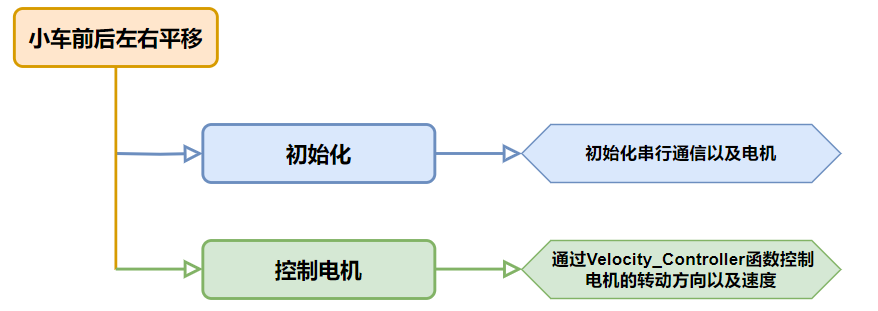
5.3 小车前后左右平移
本节通过控制M1~M4四个电机的转动方向来控制小车前后左右平移。
5.3.1 运动原理
根据麦克纳姆轮的特性,当小车轮子全部正转时,小车前进;当小车轮子全部反转时,小车后退;当A轮全部反转,B轮正转时,小车左平移;当B轮全部反转,A轮正转时,小车右平移。小车前后左右的运动受力分析图如下:
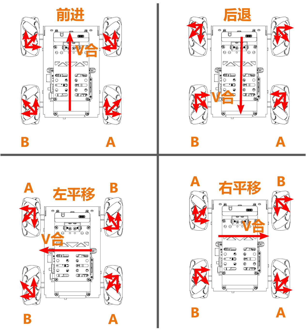
根据物理运动学知识可知,大小相等,方向相反的力可以互相抵消,假设A轮和B轮正转的速度一样快,那么A轮分解出向右的力和B轮分解出向左的力刚好互相抵消,合力方向向前,根据牛顿第二运动定律(F=ma)可知,加速度方向向前,则最终合速度方向“V合”也向前。其他方向的速度解析也是以同样的思路来推导。
5.3.2 实现流程
5.3.3 程序下载
NOTE
下载程序前需先将蓝牙模块取下,否则会因串口冲突导致程序下载失败。
- 在本文档同路径"02 程序文件\小车前后左右平移程序"下找到“left_and_right/left_and_right.ino”程序文件。

将Arduino通过UNO数据线(Type-B)连接至电脑。
点击“选择开发板”选项,软件会自动检测当前Arduino的串口,点击进行连接。
- 点击,将程序下载至Arduino中,等待下载完成即可。
5.3.4 实现效果
程序下载完成后,将小车开机,小车将前进1S->后退1S->向左平移1S->向右平移1S。
5.3.5 程序分析
- 定义引脚及创建对象
- 定义
motorpwmPin数组,存储4个电机的PWM控制引脚号;定义motordirectionPin数组,用于存储4个电机的方向控制引脚号。
#include <Arduino.h>

const static uint8_t pwm_min = 50;
const static uint8_t motorpwmPin[4] = { 10, 9, 6, 11};            ///< 控制轮子速度引脚
const static uint8_t motordirectionPin[4] = { 12, 8, 7, 13}; ///< 控制轮子方向引脚- 声明了三个函数原型,
Motor_Init电机初始化、Velocity_Controller速度控制、Motors_Set设置电机速度。
void Motor_Init(void);
void Velocity_Controller(uint16_t angle, uint8_t velocity,int8_t rot,bool drift);
void Motors_Set(int8_t Motor_0, int8_t Motor_1, int8_t Motor_2, int8_t Motor_3);- setup()初始化及运动控制
- 初始化串行通信,设置串行通信读取数据超时时间为500ms;调用
Motor_Int()函数初始化电机。
void setup() {
  Serial.begin(9600);
  // 设置串行端口读取数据的超时时间
  Serial.setTimeout(500);
Motor_Init(); ///< 电机初始化- 调用
Velocity_Controller函数,设置电机以前进模式运行,速度为100,然后等待1秒。
  Velocity_Controller(0,100,0,0);  ///< 前进
delay(1000);- 调用
Velocity_Controller函数,设置电机以后退模式运行,速度为100,然后等待1秒。
  Velocity_Controller(180,100,0,0);  ///< 后退
delay(1000);- 调用
Velocity_Controller函数,设置电机以原地左平移模式运行,速度为100,然后等待1秒。
  Velocity_Controller(90,100,0,0);  ///< 左移
delay(1000);- 调用
Velocity_Controller函数,设置电机以原地右平移模式运行,速度为100,然后等待1秒。
  Velocity_Controller(270,100,0,0); ///< 右移
delay(1000);- 调用
Velocity_Controller函数,设置电机静止。
  Velocity_Controller(0,0,0,0);     ///< 静止
}- Motor_Init()电机初始化函数
初始化了电机的方向引脚为输出模式,调用Velocity_Controller函数,设置电机静止。
void Motor_Init(void){
  for(uint8_t i = 0; i < 4; i++){
    pinMode(motordirectionPin[i], OUTPUT);
  }
  Velocity_Controller( 0, 0, 0, 0);
}- Velocity_Controller()速度控制函数
- 初始化4个电机的速度值为整形,设置速度因子为1,将angle设为90°用于修正机器人方向,接着将angle从度转换为弧度。
void Velocity_Controller(uint16_t angle, uint8_t velocity,int8_t rot,bool drift) {
  int8_t velocity_0, velocity_1, velocity_2, velocity_3;
  float speed = 1;
  angle += 90;
float rad = angle * PI / 180;- 判断rot是否为0,若为0,则设置speed为1,否则设置speed为0.5。
  if (rot == 0) speed = 1;///< 速度因子
else speed = 0.5;- 减小速度值。
velocity /= sqrt(2);- 根据
drift的值计算4个电机的速度。
  if (drift) {
    velocity_0 = (velocity * sin(rad) - velocity * cos(rad)) * speed;
    velocity_1 = (velocity * sin(rad) + velocity * cos(rad)) * speed;
    velocity_2 = (velocity * sin(rad) - velocity * cos(rad)) * speed - rot * speed * 2;
    velocity_3 = (velocity * sin(rad) + velocity * cos(rad)) * speed + rot * speed * 2;
  } else {
    velocity_0 = (velocity * sin(rad) - velocity * cos(rad)) * speed + rot * speed;
    velocity_1 = (velocity * sin(rad) + velocity * cos(rad)) * speed - rot * speed;
    velocity_2 = (velocity * sin(rad) - velocity * cos(rad)) * speed - rot * speed;
    velocity_3 = (velocity * sin(rad) + velocity * cos(rad)) * speed + rot * speed;
}- 使用计算得到的4个电机的速度值设置电机。
  Motors_Set(velocity_0, velocity_1, velocity_2, velocity_3);
}- Motors_Set电机速度函数
- 定义存储PWM值、电机速度值、电机方向的数组。
void Motors_Set(int8_t Motor_0, int8_t Motor_1, int8_t Motor_2, int8_t Motor_3) {
  int8_t pwm_set[4];
  int8_t motors[4] = { Motor_0, Motor_1, Motor_2, Motor_3};
bool direction[4] = { 1, 0, 0, 1};///< 前进 左1 右0- 遍历4个电机,并根据电机速度值确定电机方向。
for(uint8_t i; i < 4; ++i) {
if(motors[i] < 0) direction[i] = !direction[i];
else direction[i] = direction[i];
if(motors[i] == 0) pwm_set[i] = 0;
else pwm_set[i] = map(abs(motors[i]), 0, 100, pwm_min, 255);
digitalWrite(motordirectionPin[i], direction[i]);
analogWrite(motorpwmPin[i], pwm_set[i]);
}
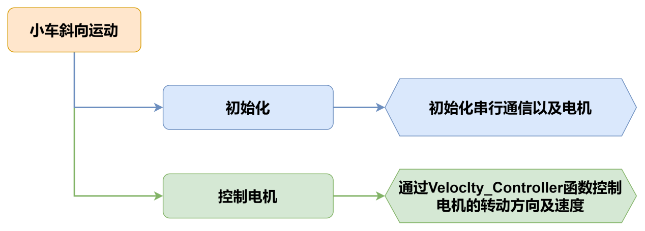
}5.4 小车斜向运动
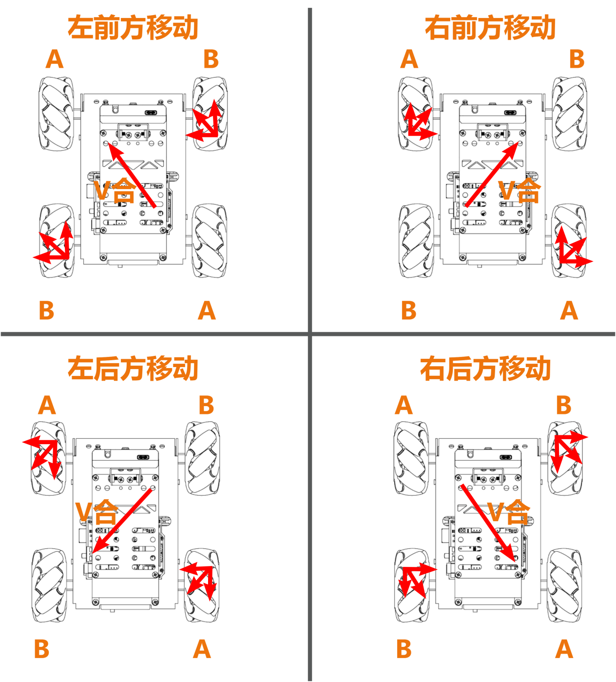
5.4.1 本节原理
根据麦克纳姆轮的特性,当小车A轮不动,B轮正转时,小车朝左前方移动;B轮反转时,小车朝右后方移动。当小车B轮不动,A轮正转时,小车朝右前方移动;A轮反转时,小车朝左后方移动。小车斜向移动受力分析图如下:
5.4.2 实现流程
5.4.3 程序下载
NOTE
下载程序前需先将蓝牙模块取下,否则会因串口冲突导致程序下载失败。
- 在本文档同路径"02 程序文件\小车斜向运动程序"下找到“slant/slant.ino”程序文件。

将Arduino通过UNO数据线(Type-B)连接至电脑。
点击“选择开发板”选项,软件会自动检测当前Arduino的串口,点击进行连接。
- 点击,将程序下载至Arduino中,等待下载完成即可。
5.4.4 实现效果
程序下载完成后,将小车开机,小车将向左前方移动1S->向右后方移动1S->向右前方移动1S->向左后方移动1S。
5.4.5 程序分析
- 定义引脚及创建对象
- 定义
motorpwmPin数组,存储4个电机的PWM控制引脚号;定义motordirectionPin数组,用于存储4个电机的方向控制引脚号。
#include <Arduino.h>

const static uint8_t pwm_min = 50;
const static uint8_t motorpwmPin[4] = { 10, 9, 6, 11};            ///< 控制轮子速度引脚
const static uint8_t motordirectionPin[4] = { 12, 8, 7, 13}; ///< 控制轮子方向引脚- 声明了三个函数原型,
Motor_Init电机初始化、Velocity_Controller速度控制、Motors_Set设置电机速度。
void Motor_Init(void);
void Velocity_Controller(uint16_t angle, uint8_t velocity,int8_t rot,bool drift);
void Motors_Set(int8_t Motor_0, int8_t Motor_1, int8_t Motor_2, int8_t Motor_3);- setup()初始化及运动控制
- 初始化串行通信,设置串行通信读取数据超时时间为500ms;调用
Motor_Int()函数初始化电机。
void setup() {
  Serial.begin(9600);
  // 设置串行端口读取数据的超时时间
  Serial.setTimeout(500);
Motor_Init(); ///< 电机初始化- 调用
Velocity_Controller函数,设置电机以左前方移动模式运行,速度为100,然后等待1秒。
  Velocity_Controller(45,100,0,0);  ///< 左前方移动
delay(1000);- 调用
Velocity_Controller函数,设置电机以右后方移动模式运行,速度为100,然后等待1秒。
  Velocity_Controller(225,100,0,0); ///< 右后方移动
delay(1000);- 调用
Velocity_Controller函数,设置电机以右前方移动模式运行,速度为100,然后等待1秒。
  Velocity_Controller(315,100,0,0); ///< 右前方移动
delay(1000);- 调用
Velocity_Controller函数,设置电机以左后方移动模式运行,速度为100,然后等待1秒。
  Velocity_Controller(135,100,0,0); ///< 左后方移动
delay(1000);- 调用
Velocity_Controller函数,设置电机静止。
  Velocity_Controller(0,0,0,0);     ///< 静止
}- Motor_Init()电机初始化函数
初始化了电机的方向引脚为输出模式,调用Velocity_Controller函数,设置电机静止。
void Motor_Init(void){
  for(uint8_t i = 0; i < 4; i++){
    pinMode(motordirectionPin[i], OUTPUT);
  }
  Velocity_Controller( 0, 0, 0, 0);
}- Velocity_Controller()速度控制函数
- 初始化4个电机的速度值为整形,设置速度因子为1,将angle设为90°用于修正机器人方向,接着将angle从度转换为弧度。
void Velocity_Controller(uint16_t angle, uint8_t velocity,int8_t rot,bool drift) {
  int8_t velocity_0, velocity_1, velocity_2, velocity_3;
  float speed = 1;
  angle += 90;
float rad = angle * PI / 180;- 判断rot是否为0,若为0,则设置speed为1,否则设置speed为0.5。
  if (rot == 0) speed = 1;///< 速度因子
else speed = 0.5;- 减小速度值。
velocity /= sqrt(2);- 根据
drift的值计算4个电机的速度。
  if (drift) {
    velocity_0 = (velocity * sin(rad) - velocity * cos(rad)) * speed;
    velocity_1 = (velocity * sin(rad) + velocity * cos(rad)) * speed;
    velocity_2 = (velocity * sin(rad) - velocity * cos(rad)) * speed - rot * speed * 2;
    velocity_3 = (velocity * sin(rad) + velocity * cos(rad)) * speed + rot * speed * 2;
  } else {
    velocity_0 = (velocity * sin(rad) - velocity * cos(rad)) * speed + rot * speed;
    velocity_1 = (velocity * sin(rad) + velocity * cos(rad)) * speed - rot * speed;
    velocity_2 = (velocity * sin(rad) - velocity * cos(rad)) * speed - rot * speed;
    velocity_3 = (velocity * sin(rad) + velocity * cos(rad)) * speed + rot * speed;
}- 使用计算得到的4个电机的速度值设置电机。
  Motors_Set(velocity_0, velocity_1, velocity_2, velocity_3);
}- Motors_Set电机速度函数
- 定义存储PWM值、电机速度值、电机方向的数组。
void Motors_Set(int8_t Motor_0, int8_t Motor_1, int8_t Motor_2, int8_t Motor_3) {
  int8_t pwm_set[4];
  int8_t motors[4] = { Motor_0, Motor_1, Motor_2, Motor_3};
bool direction[4] = { 1, 0, 0, 1};///< 前进 左1 右0- 遍历4个电机,并根据电机速度值确定电机方向。
  for(uint8_t i; i < 4; ++i) {
    if(motors[i] < 0) direction[i] = !direction[i];
    else direction[i] = direction[i];

    if(motors[i] == 0) pwm_set[i] = 0;
    else pwm_set[i] = map(abs(motors[i]), 0, 100, pwm_min, 255);

    digitalWrite(motordirectionPin[i], direction[i]);
    analogWrite(motorpwmPin[i], pwm_set[i]);
  }
}
5.5 小车漂移运动
5.5.1 本节原理
根据麦克纳姆轮的特性,前面轮子不动时,后面A轮正转,B轮反转,小车逆时针漂移;后面B轮正转,A轮反转,小车顺时针漂移。小车漂移的受力分析图如下:
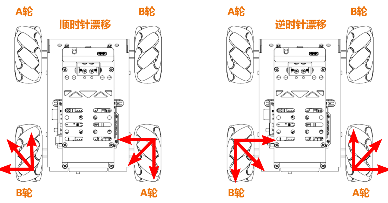
根据物理运动学知识可知,大小相等,方向相反的力可以互相抵消,以逆时针漂移为例,假设A轮和B轮转动的速度一样快,那么A轮分解出向上的力和B轮分解出向下的力刚好互相抵消,合力方向向右。
根据牛顿第二运动定律(F=ma)可知,加速度方向向右,则最终合速度方向也向右,而前轮不动,则会产生漂移。顺时针漂移也是同样的思路推导。
5.5.2 实现流程

5.5.3 程序下载
NOTE
下载程序前需先将蓝牙模块取下,否则会因串口冲突导致程序下载失败。
- 在本文同路径"02 程序文件\小车漂移运动程序"下找到“drift/drift.ino”程序文件。

将Arduino通过UNO数据线(Type-B)连接至电脑。
点击“选择开发板”选项,软件会自动检测当前Arduino的串口,点击进行连接。
- 点击,将程序下载至Arduino中,等待下载完成即可。
5.5.4 实现效果
程序下载完成后,将小车开机,小车将原地漂移。
5.5.5 程序分析
- 定义引脚及创建对象
- 定义
motorpwmPin数组,存储4个电机的PWM控制引脚号;定义motordirectionPin数组,用于存储4个电机的方向控制引脚号。
#include <Arduino.h>

const static uint8_t pwm_min = 50;
const static uint8_t motorpwmPin[4] = { 10, 9, 6, 11};            ///< 控制轮子速度引脚
const static uint8_t motordirectionPin[4] = { 12, 8, 7, 13}; ///< 控制轮子方向引脚- 声明了三个函数原型,
Motor_Init电机初始化、Velocity_Controller速度控制、Motors_Set设置电机速度。
void Motor_Init(void);
void Velocity_Controller(uint16_t angle, uint8_t velocity,int8_t rot,bool drift);
void Motors_Set(int8_t Motor_0, int8_t Motor_1, int8_t Motor_2, int8_t Motor_3);- setup()初始化及运动控制
- 初始化串行通信,设置串行通信读取数据超时时间为500ms;调用
Motor_Int()函数初始化电机。
void setup() {
  Serial.begin(9600);
  // 设置串行端口读取数据的超时时间
  Serial.setTimeout(500);
Motor_Init(); ///< 电机初始化- 调用
Velocity_Controller函数,设置电机以漂移模式运行,速度为100,然后等待1秒。
  Velocity_Controller(0,0,60,true);  ///< 漂移到物块的对面
delay(3000); //转半圈的时间- 调用
Velocity_Controller函数,设置电机静止。
Velocity_Controller(0,0,0,0); ///< 静止- Motor_Init()电机初始化函数
初始化了电机的方向引脚为输出模式,调用Velocity_Controller函数,设置电机静止。
void Motor_Init(void){
  for(uint8_t i = 0; i < 4; i++){
    pinMode(motordirectionPin[i], OUTPUT);
  }
  Velocity_Controller( 0, 0, 0, 0);
}- Velocity_Controller()速度控制函数
- 初始化4个电机的速度值为整形,设置速度因子为1,将angle设为90°用于修正机器人方向,接着将angle从度转换为弧度。
void Velocity_Controller(uint16_t angle, uint8_t velocity,int8_t rot,bool drift) {
  int8_t velocity_0, velocity_1, velocity_2, velocity_3;
  float speed = 1;
  angle += 90;
float rad = angle * PI / 180;- 判断rot是否为0,若为0,则设置speed为1,否则设置speed为0.5。
  if (rot == 0) speed = 1;///< 速度因子
else speed = 0.5;- 减小速度值。
velocity /= sqrt(2);- 根据drift的值计算4个电机的速度。
  if (drift) {
    velocity_0 = (velocity * sin(rad) - velocity * cos(rad)) * speed;
    velocity_1 = (velocity * sin(rad) + velocity * cos(rad)) * speed;
    velocity_2 = (velocity * sin(rad) - velocity * cos(rad)) * speed - rot * speed * 2;
    velocity_3 = (velocity * sin(rad) + velocity * cos(rad)) * speed + rot * speed * 2;
  } else {
    velocity_0 = (velocity * sin(rad) - velocity * cos(rad)) * speed + rot * speed;
    velocity_1 = (velocity * sin(rad) + velocity * cos(rad)) * speed - rot * speed;
    velocity_2 = (velocity * sin(rad) - velocity * cos(rad)) * speed - rot * speed;
    velocity_3 = (velocity * sin(rad) + velocity * cos(rad)) * speed + rot * speed;
}- 使用计算得到的4个电机的速度值设置电机。
  Motors_Set(velocity_0, velocity_1, velocity_2, velocity_3);
}- Motors_Set电机速度函数
- 定义存储PWM值、电机速度值、电机方向的数组。
void Motors_Set(int8_t Motor_0, int8_t Motor_1, int8_t Motor_2, int8_t Motor_3) {
  int8_t pwm_set[4];
  int8_t motors[4] = { Motor_0, Motor_1, Motor_2, Motor_3};
bool direction[4] = { 1, 0, 0, 1};///< 前进 左1 右0- 遍历4个电机,并根据电机速度值确定电机方向。
  for(uint8_t i; i < 4; ++i) {
    if(motors[i] < 0) direction[i] = !direction[i];
    else direction[i] = direction[i];

    if(motors[i] == 0) pwm_set[i] = 0;
    else pwm_set[i] = map(abs(motors[i]), 0, 100, pwm_min, 255);

    digitalWrite(motordirectionPin[i], direction[i]);
    analogWrite(motorpwmPin[i], pwm_set[i]);
  }
}
5.5.6 功能延伸
程序默认是原地漂移,我们这里将程序修改为原地自转,具体的修改步骤如下:
- 将
setup()函数中Velocity_Controller()函数中drift参数修改为0即可。
Velocity_Controller(0,0,60,0);- 参照“5.5.3程序下载”将程序下载,再次开机即可查看修改后的效果。